Decoding the Integration of Transformer PCB Design: A Comprehensive Analysis
Transformers are integral parts of many electronics applications, yet their integration onto printed circuit boards (PCBs) presents unique challenges due to their inherent complexities and space restrictions. Understanding these aspects will provide electronics designers with an immense edge.
Before delving deeper into how transformers can be implemented in PCB design, let’s explore their purpose and function. Transformers are devices which transfer electrical energy from one circuit to the next through electromagnetic induction. They serve various functions on PCBs including voltage stepping, impedance matching, isolation, and signal processing.
Integration of transformers onto PCBs requires careful thought when it comes to their placement, routing and insulation – each aspect can have an enormous effect on overall performance of the board.
1. Transformer Installation:
Transformer placement is an integral component of PCB layout. Given their large sizes, transformers often mark the starting point for designs. Designers must take into account thermal properties, magnetic fields and potential mechanical stress when placing transformers – this can reduce potential interference and extend their longevity in a PCB system.
2. Routing Transformers:
Routing is the practice of designing the path for electrical connections on a PCB. Transformers typically contain both high voltage and low voltage sides that should be carefully routed in order to prevent noise interference; high-voltage should be routed first followed by low-voltage, keeping their distance as far apart as possible from each other; additionally power and ground planes should not be placed underneath a transformer in order to reduce capacitive coupling between its core and ground plane.
3. Transformer Insulation:
Insulation is essential to protecting transformers from failure due to factors like humidity, voltage overloads or temperature fluctuations. Depending on your application and desired insulation materials and methods may be utilized; common methods include vacuum pressure impregnation, encapsulation and conformal coating – selecting an insulation method depends upon various considerations such as transformer voltage, application and its environment in which it will operate.
The above guidelines offer a general roadmap towards successfully incorporating transformers in PCB design, but there can be unique challenges associated with their incorporation, including managing space constraints, heat dissipation issues and potential electromagnetic interference (EMI).
To effectively address these challenges, a number of best practices should be utilized. These include allocating appropriate space for the transformer, using heat sinks or thermal vias for temperature management and employing shielding techniques to minimize electromagnetic interference (EMI). Furthermore, using simulation tools during design can help identify any potential issues early and save valuable time and resources.
Integrating transformers into PCB designs may present its own set of unique challenges; however, with careful planning and the implementation of best practices these obstacles can be overcome successfully. Learning the art of transformer integration opens up a variety of design opportunities in PCB creation while increasing capabilities and providing access to advanced electronics solutions.
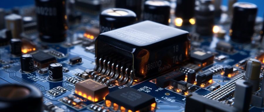
Professional or hobbyist alike, understanding the role and methods for using transformers on printed circuit boards (PCBs) effectively is a necessary skill set in electronic design. Through our knowledge of these transformers we can develop more sophisticated, reliable, and high-performing electronic devices – one transformer at a time!
Transformer PCB FAQ:
- What is a transformer PCB?
In the context of a Printed Circuit Board (PCB), a transformer is a passive electrical component used to transfer energy between two or more circuits through electromagnetic induction. It is often used for stepping voltage up or down, isolation, or impedance matching. - How are transformers mounted on a PCB?
Transformers can be soldered directly onto the PCB or mounted using pins that go through the board and are soldered in place. They can be surface mount style or through-hole depending on the design needs. - Are there specific transformers PCBs?
Yes, there are specific transformers designed for PCB mounting, these are often smaller than traditional transformers. They might be planar transformers with a flat design, or toroidal transformers with a compact, circular shape. - What’s the role of a transformer PCB?
The primary role of a transformer PCB is to ensure the correct voltage is supplied to components. They also provide isolation between circuits to prevent electrical noise interference, help reduce electrical shock risk in certain applications and help in impedance matching. - What are some common applications of transformer PCBs?
Transformers are used in various applications such as power supply circuits, audio circuits, RF circuits, and digital circuits. They are especially common in power electronics and communication systems. - How do I choose a transformer PCB?
Selecting a transformer requires you to consider several factors such as the input and output voltage requirements, power rating, working frequency, transformer type (power transformer, audio transformer etc.), mounting style, and size requirements. - Are there layout considerations when placing a transformer PCB?
Yes, transformers can create electromagnetic interference (EMI) that can affect other components. Therefore, transformers should be placed keeping in mind to minimize this impact. Also, paths for high current should be kept short and wide to minimize resistance and inductive losses. - Are there risks associated with using transformer PCBs?
While transformers are generally safe and reliable, they can pose risks if improperly specified or used. For example, a transformer with a higher power rating than the board can handle may overload and damage the board. - Can I use multiple transformer PCB?
Yes, it is not uncommon to see multiple transformers on a single PCB especially in complex systems, each serving different circuits or subsystems. - How do I connect a transformer PCB?
Transformers have primary and secondary windings which will have connection points or pins. These pins are used to connect the transformer to the PCB either by soldering directly to the PCB or using compatible connectors or through-holes provided in the PCB.

