How to Test PCB Board with Multimeter? 8 Chapters Tell You
With the advent of technology, Printed Circuit Boards (PCBs) have become a crucial component in almost all electronic devices, from your smartphone to your refrigerator. The health and performance of these gadgets depend heavily on the proper functioning of their respective PCBs. As such, the ability to test a PCB board using a multimeter is an essential skill for electronic enthusiasts and professionals alike. In this comprehensive guide, we walk you through the process step by step, ensuring you gain both the knowledge and confidence to do it yourself.
How to Test PCB Board with Multimeter? Chapter 1: Getting Started with PCB and Multimeters
Before we delve into the testing process, let’s first understand what a PCB Board and a multimeter are, and why they’re crucial in the electronic world.
What is a PCB?
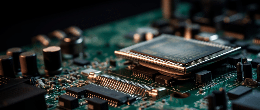
A PCB, or Printed Circuit Board, is an intricate network of interconnections helping different parts of an electronic device communicate with each other. It physically supports and electrically connects electronic components through conductive tracks, pads, and other features etched from copper sheets and laminated onto non-conductive substrate.
What is a Multimeter?
A Multimeter is a versatile tool used to measure electrical properties like voltage, current, and resistance. It can be digital or analog. Whether you are a hobbyist or a professional, a multimeter is an indispensable tool when working with electronics.
How to Test PCB Board with Multimeter? Chapter 2: The Importance of Testing a PCB
It is crucial to test a PCB for continuity, resistance, and voltage to ensure correct trace connections and the absence of shorts or broken paths. By testing a PCB, you can effectively diagnose and fix circuit board failures, improving reliability and performance.
How to Test PCB Board with Multimeter? Chapter 3: Testing PCB Boards with Multimeter
Now to the core of this guide – testing a PCB board with a multimeter.
Continuity Test
- After turning off and unplugging the device, remove the PCB from the device, making sure to remember or note down where each connector and component goes.
- Set your multimeter to continuity mode (signified by a diode symbol or wave line, depending on your multimeter brand).
- Place the multimeter leads on the specific paths you want to test for continuity. If the multimeter beeps, it indicates that the path is continuous, which is a good sign.
Resistance Test
- Set your multimeter to measure resistance, signified by the Ohm symbol (Ω).
- Place the multimeter leads on each end of the resistor leg on the board. The multimeter should read near to the resistor’s value. If it doesn’t, the resistor could be faulty.
Voltage Test
- Power the PCB (be careful as this could expose you to dangerous voltage levels).
- Set the multimeter to measure the DC or AC voltage depending on the power source of your circuit board.
- Place the red lead on the power pin and the black one on a ground pin. The multimeter should display the power source voltage.
Through the detailed process above, you can effectively and safely use a multimeter to test your PCB Board for continuity, resistance, and voltage, ensuring its functionality and the optimal performance of your device.
How to Test PCB Board with Multimeter? Chapter 4: Safety Measures When Testing PCBs
When dealing with electronics, safety should always be a priority. This chapter focuses on essential safety measures when testing PCBs.
Remember to always switch off and unplug the device before removing the PCB. When testing for voltage, be aware of the potential risk of electric shock and handle the setup cautiously. Always adhere to the manufacturer’s instructions and safety guidelines while using a multimeter or handling PCBs.
How to Test PCB Board with Multimeter? Chapter 5: Common Problems and Troubleshooting
This chapter discusses common issues that you may face when dealing with PCB boards and potential solutions to these issues. Understanding this beforehand can save you time and frustration when performing your tests.
Navigating this complex but crucial world of PCBs and multimeters, you now have the knowledge to efficiently test your PCB board using a multimeter. This essential skill not only allows you to diagnose and fix potential circuit board failures but also empowers you to verify the functionality and performance of your electronic devices.
How to Test PCB Board with Multimeter? Chapter 6: Advanced Techniques in Testing PCB
As you get comfortable with basic continuity, resistance, and voltage tests, you may want to delve deeper into PCB testing. This chapter discusses some advanced techniques, including testing for capacitance, frequency, and temperature, further expanding your multimeter skills. Remember, each new technique learned brings you a step closer to becoming an electronics wizard.
How to Test PCB Board with Multimeter? Chapter 7: When to Involve a Professional
While this guide aims to empower you to conduct these tests independently, there may be situations where professional help is necessary. Recognizing when to involve a professional is crucial to avoid potential damage to your PCB boards or, in worst-case scenarios, personal injury. This chapter discusses scenarios where seeking professional help would be prudent.
How to Test PCB Board with Multimeter? Chapter 8: Future of PCB Testing
The world of electronics is ever-evolving, and so are the techniques used in PCB testing. This chapter delves into intriguing future trends of PCB testing, including automated testing and boundary-scan technology. Staying ahead of these trends ensures that you remain relevant and informed in the dynamic arena of electronics.
By now, whether you’re an electronics enthusiast or a professional, you should confidently use a multimeter to test a PCB board. Remember, practice makes perfect. So get your multimeter, roll up your sleeves, and let’s enhance the lifespans of our gadgets together!
This comprehensive guide is your first step into the fascinating world of PCBs and multimeters. But remember, learning is a lifelong journey. May you never stop exploring, questioning, and innovating. After all, in the field of electronics, there’s always a new mystery waiting to be unraveled!
Closing Statement:
We hope this guide on how to test a PCB board with a multimeter has been informative and helpful. Remember, safety first, always! Understanding and efficient testing of PCBs will continue to be an essential skill as we forge ahead in our tech-dependent world.
FAQ:
- 1. What is a PCB test?
A PCB test is an examination process to inspect the functionality and integrity of Printed Circuit Boards (PCBs) to ensure they are working perfectly without any errors. - Why is a PCB test necessary?
The PCB test is necessary to identify any components’ malfunctions, broken circuits, short circuits, or potential problems, preventing issues after the product’s deployment. - What methods are used for PCB testing?
There are several methods for testing, such as visual inspection, automated optical inspection, in-circuit test, functional test, flying probe test, boundary scan test, etc. - What is an In-Circuit Test (ICT)?
ICT is a type of PCB test that checks each component individually for proper value and operation while it’s on the board. - What is a Functional PCB Test?
A functional test is a type of PCB test where the functionality of the circuit board is tested under different conditions to ensure it meets the required specifications. - What is a Flying Probe Test?
A Flying Probe Test is a testing method that doesn’t require any dedicated tooling or fixtures. It uses moving probes to test the electrical performance of components and circuits. - Is manual testing used in PCB testing?
Yes, manual visual inspection is a basic method often used in PCB testing, though it can be time-consuming and less precise than automated methods. - Can PCB testing detect manufacturing defects?
Yes, PCB testing not only checks for component functionality but also identifies manufacturing defects such as bad solder joints, component misplacements, and short or open circuits. - How long does a PCB test take?
The duration of a PCB test can vary widely and depends on the complexity of the board, the number of components, and the type of test being conducted. - Is PCB testing done on all circuit boards before they’re sold?
Usually, manufacturers perform testing on all PCBs to ensure quality and functionality. However, it might vary from manufacturer to manufacturer and their quality assurance standards.

